


1.完整项目描述和程序获取
>面包多安全交易平台:https://mbd.pub/o/bread/ZJaXmZpr
>如果链接失效,可以直接打开本站店铺搜索相关店铺:
>如果链接失效,程序调试报错或者项目合作也可以加微信或者QQ联系。
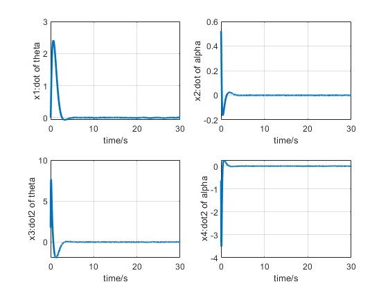
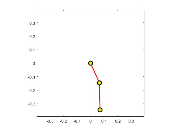
2.部分仿真图预览
3.算法概述
倒立摆控制,使摆杆尽快达到平衡位置,且无大的振荡和过大的角度和速度的控制系统。当摆杆到达期望位置后,系统能克服随机扰动而保持稳定。该控制系统的输入为小车的位移(即位置)和摆杆的倾斜角度期望值,计算机在每一个采样周期中采集来自传感器的小车与摆杆的实际位置信号,与期望值进行比较后,通过控制算法得到控制量,再经数模转换驱动直流电机实现倒立摆的实时控制。按摆杆数量,分为一级、二级、三级倒立摆等。该系统是一个复杂的、不稳定的非线性系统,是进行控制理论研究的理想实验平台。
4.部分源码
.................................................................
global Jb;
global lp;
global mp;
global g;
LEN= 10000;
%离散
ts = 0.01;
mp = 0.17;
r = 0.16;
Jb = 0.0024;
R = 8.3;
Km = 0.023;
Kg = 120/16;
lp = 0.2;
g = 9.8;
%根据
a1 = -mp*r*g/Jb;
a2 = -Kg^2*Km^2/R/Jb;
a3 = g*(Jb + mp*r^2)/lp/Jb;
a4 = r*Kg*Kg*Km*Km/R/lp/Jb;
b1 = Kg*Km/R/Jb;
b2 = -r*Kg*Km/R/lp/Jb;
A = [0,0 ,1 ,0;
0,0 ,0 ,1;
0,a1,a2,0;
0,a3,a4,0];
B = [0;
0
b1;
b2];
[F,G] = c2d(A,B,ts);
Q = diag([1 1 0 0]);
R = [1];
[K,p,e] = dlqr(F,G,Q,R);
F = F-G*K;
%初始条件
x1_0 = 0;
x2_0 = pi/2;
x3_0 = 0;
x4_0 = pi/2;
u_0 = 10;
for k=1:1:LEN
k
.........................................................................
%PF
X(k) = func_ukf_filter(y);
u_0 = X(k);
x1_0 = x1(k);
x2_0 = x2(k);
x3_0 = x3(k);
x4_0 = x4(k);
end
figure;
subplot(221);
plot(time(1:3000),x1(1:3000),'linewidth',2);
xlabel('time/s');
ylabel('x1:dot of theta');
grid on;
subplot(222);
plot(time(1:3000),x2(1:3000),'linewidth',2);
xlabel('time/s');
ylabel('x2:dot of alpha');
grid on;
subplot(223);
plot(time(1:3000),x3(1:3000),'linewidth',2);
xlabel('time/s');
ylabel('x3:dot2 of theta');
grid on;
subplot(224);
plot(time(1:3000),x4(1:3000),'linewidth',2);
xlabel('time/s');
ylabel('x4:dot2 of alpha');
grid on;
figure;
plot(time(1:3000),X(1:3000),'linewidth',2);
xlabel('time/s');
ylabel('the output of controler');
grid on;
save thetad2.mat x1 time X
save alphad2.mat x2 time X
save thetadd2.mat x3 time X
save alphadd2.mat x4 time X
%根据控制效果,画出动画
X1 = [time;x1];
X2 = [time;x2];
X3 = [time;x3];
X4 = [time;x4];
phi1 = x1;
dtphi1 = x3;
phi2 = x2;
dtphi2 = x4;
l1=r;
l2=lp;
figure;
h=plot(0,0,'-ro',...
'LineWidth',2,...
'MarkerSize',10,...
'MarkerEdgeColor','k',...
'MarkerFaceColor',[0.9,0.9,0.0]);
range=1.1*(l1+l2); axis([-range range -range range]);
axis square;
set(gca,'nextplot','replacechildren');
for i=1:min(length(phi1)-1,200)
if (ishandle(h)==1)
Xcoord=[0,l1*sin(phi1(i)),l1*sin(phi1(i))+l2*sin(phi2(i))];
Ycoord=[0,-l1*cos(phi1(i)),-l1*cos(phi1(i))-l2*cos(phi2(i))];
set(h,'XData',Xcoord,'YData',Ycoord);
pause(0.1);
end
end
08_032_m