


1.完整项目描述和程序获取
>面包多安全交易平台:https://mbd.pub/o/bread/Z56alZpv
>如果链接失效,可以直接打开本站店铺搜索相关店铺:
>如果链接失效,程序调试报错或者项目合作也可以加微信或者QQ联系。
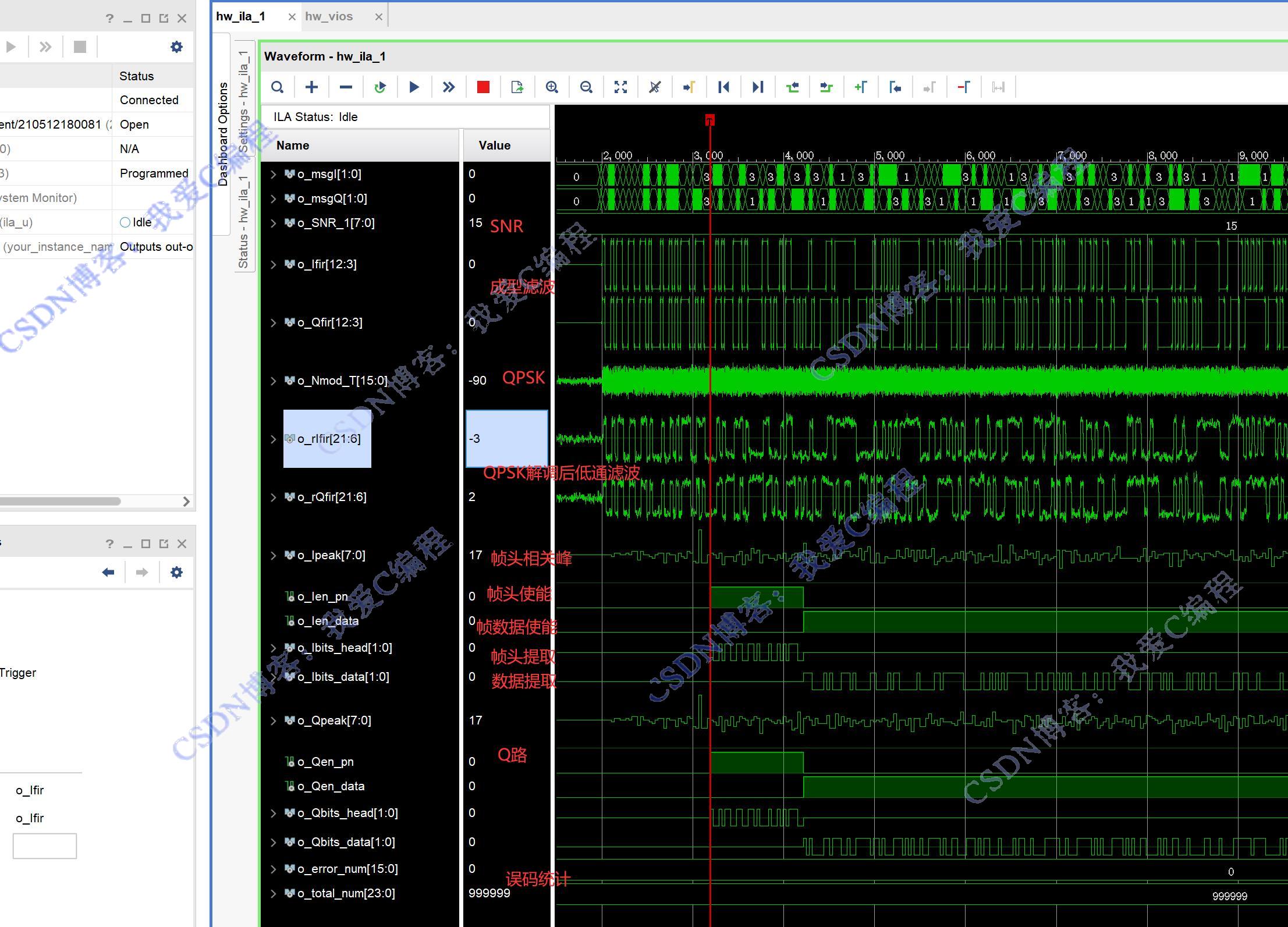
2.部分仿真图预览
3.算法概述
在数字通信中,信息通常是以帧为单位进行组织和传输的。帧同步的目的是确定每一帧的起始位置,以便接收端能够正确地解调出每帧中的数据。
设发送的帧结构为:帧同步码 + 信息码元序列 。帧同步码是具有特定规律的码序列,用于接收端识别帧的起始。
帧同步的过程就是在接收序列中寻找与帧同步码匹配的位置,一旦找到匹配位置,就确定了帧的起始位置,后续的码元就可以按照帧结构进行正确的划分和处理。
4.部分源码
`timescale 1ns / 1ps
//
// Company:
// Engineer:
//
// Create Date: 2024/11/04 19:54:30
// Design Name:
// Module Name: tops_hdw
// Project Name:
// Target Devices:
// Tool Versions:
// Description:
//
// Dependencies:
//
// Revision:
// Revision 0.01 - File Created
// Additional Comments:
//
//
module tops_hdw(
input i_clk,
input i_rst,
output reg [3:0] led
);
//产生模拟测试数据
wire signed[1:0]o_msgI;
wire signed[1:0]o_msgQ;
signaler signaler_u(
.i_clk (i_clk),
.i_rst (~i_rst),
.o_bits1(o_msgI),
.o_bits2(o_msgQ)
);
//设置SNR
wire signed[7:0]o_SNR;
vio_0 your_instance_name (
.clk(i_clk), // input wire clk
.probe_out0(o_SNR) // output wire [7 : 0] probe_out0
);
wire signed[15:0]o_Ifir;
wire signed[15:0]o_Qfir;
wire signed[15:0]o_Nmod_T;
wire signed[31:0]o_rmodc;
wire signed[31:0]o_rmods;
wire signed[31:0]o_rIfir;
wire signed[31:0]o_rQfir;
wire [1:0]o_Ibits_data;
wire [1:0]o_Ibits_head;
wire [7:0]o_Ipeak;
wire o_Ien_data;
wire o_Ien_pn;
wire [1:0]o_Qbits_data;
wire [1:0]o_Qbits_head;
wire [7:0]o_Qpeak;
wire o_Qen_data;
wire o_Qen_pn;
wire signed[31:0]o_error_num;
wire signed[31:0]o_total_num;
QPSK_tops uut(
.i_clk (i_clk),
.i_rst (~i_rst),
.i_Ibits (o_msgI),
.i_Qbits (o_msgQ),
.i_SNR (o_SNR),
.o_Ifir (o_Ifir),
.o_Qfir (o_Qfir),
.o_mod_T (),
.o_Nmod_T (o_Nmod_T),
.o_rmodc(o_rmodc),
.o_rmods(o_rmods),
.o_rIfir(o_rIfir),
.o_rQfir(o_rQfir),
.o_Ibits_data (o_Ibits_data),
.o_Ibits_head (o_Ibits_head),
.o_Ipeak (o_Ipeak),
.o_Ien_data (o_Ien_data),
.o_Ien_pn (o_Ien_pn),
.o_Iframe_start (),
.o_Qbits_data (o_Qbits_data),
.o_Qbits_head (o_Qbits_head),
.o_Qpeak (o_Qpeak),
.o_Qen_data (o_Qen_data),
.o_Qen_pn (o_Qen_pn),
.o_Qframe_start (),
.o_error_num (o_error_num),
.o_total_num (o_total_num)
);
//ila篇内测试分析模块140
ila_0 ila_u (
.clk(i_clk), // input wire clk
.probe0({
o_msgI,o_msgQ,o_SNR,o_Ifir[15:6],o_Qfir[15:6],//30
o_Nmod_T,o_rIfir[27:12],o_rQfir[27:12],//48
o_error_num[15:0],o_total_num[23:0],//40
//28
o_Ien_pn,
o_Ien_data,
o_Ipeak,
o_Ibits_head,
o_Ibits_data,
o_Qen_pn,
o_Qen_data,
o_Qpeak,
o_Qbits_head,
o_Qbits_data
})
);
endmodule
0sj_059m
---